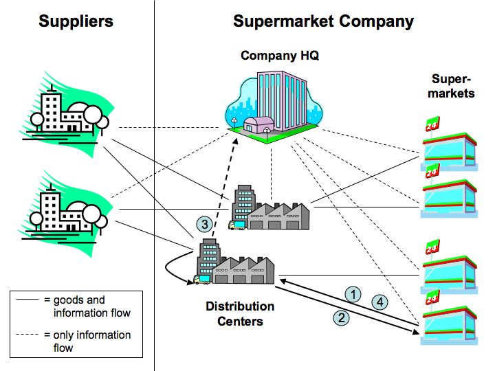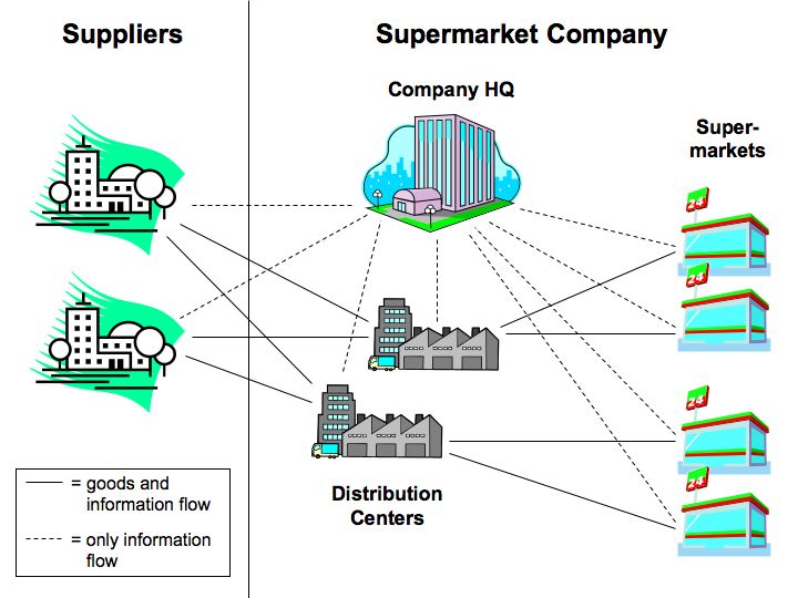
FIGURE 1: SPECjms2007 Supermarket Supply Chain
The major goal of the SPECjms2007 benchmark is to provide a standard workload and metrics for measuring and evaluating the performance and scalability of JMS-based Message-Oriented Middleware (MOM) platforms. In addition, the benchmark should provide a flexible framework for JMS performance analysis. To achieve this goal, the SPECjms2007 workload must meet several important requirements:
No matter how well a benchmark is designed, it would be of little value if the workload it is based on does not reflect the way platform services are exercised in real-life systems. Therefore, the most important requirement for the SPECjms2007 benchmark is that it is based on a representative workload scenario including a representative set of interactions, message types, message sizes and message delivery modes. The communication style and the types of messages sent and received by the different parties in the scenario should represent a typical transaction mix. The goal is to allow users to relate the observed behavior to their own applications and environments.
The second important requirement is that the workload is comprehensive in that it should exercise all platform features typically used in the major classes of JMS applications including both point-to-point (P2P) and publish/subscribe (pub/sub) messaging. The features and services stressed should be weighted according to their usage in real-life systems. There is no need to cover features of MOM platforms that are used very rarely in practice.
The following dimensions have to be considered when defining the workload transaction mix:
The workload should be focused on measuring the performance and scalability of the JMS Server's software and hardware components. It should minimize the impact of other components and services that are typically used in the chosen application scenario. For example, if a database would be used to store business data and manage the application state, it could easily become the limiting factor of the benchmark. This is especially true in the case of SPECjms2007, since JMS Servers, in their role as mediators in interactions, are typically less loaded than database or application servers. Another potential concern is the Client side of the benchmark where messages are sent and received. The impact of Client-side operations, such as XML parsing, on the overall performance of the benchmark should be minimized.
As mentioned above, in addition to providing standard workload and metrics for JMS performance, SPECjms2007 aims to provide a flexible performance analysis framework which allows users to configure and customize the workload according to their requirements. Producing and publishing standard results for marketing purposes is just one usage scenario for SPECjms2007. Many users would be interested in using the benchmark to tune and optimize their platforms or to analyze the performance of certain specific MOM features. Others could use the benchmark for research purposes in academic environments where, for example, one might be interested in evaluating the performance and scalability of novel methods and techniques for building high-performance MOM servers. All these usage scenarios require that the benchmark framework allows the user to precisely configure the workload and transaction mix to be generated. Providing this configurability is a great challenge because it requires that interactions are designed and implemented in such a way that one could run them in different combinations depending on the desired transaction mix. The ability to switch interactions off implies that interactions should be decoupled from one another. On the other hand, it should be ensured that the benchmark, when run in its standard mode, behaves as if the interactions were interrelated according to their dependencies in the real-life application scenario.
The SPECjms2007 application scenario must provide a way to scale the workload along the following two dimensions:
In the Horizontal scaling, the workload is scaled by increasing the number of Destinations (queues and topics) while keeping the traffic per Destination constant. In the Vertical scaling, the traffic (in terms of message count) pushed through a Destination is increased while keeping the number of Destinations fixed. Both types of scaling should be supported in a manner that preserves the relation to the real-life business scenario modeled. In addition, the user should be offered the possibility to scale the workload in an arbitrary manner by increasing the number of Destinations (queues and topics) and/or the message traffic pushed through a Destination.
The application scenario chosen for SPECjms2007 models the supply chain of a supermarket company. The participants involved are the supermarket company, its stores, its distribution centers and its suppliers. The scenario was defined based on the requirements discussed in the previous section. It offers an excellent basis for defining interactions that stress different subsets of the functionality offered by JMS Servers, e.g. different message types as well as both P2P and pub/sub communication. The scenario also offers a natural way to scale the workload, e.g. by scaling the number of Supermarkets (Horizontal) or by scaling the amount of products sold per Supermarket (Vertical).
The participants involved in the scenario can be grouped into the following four roles:
The first three roles are owned by the supermarket company and therefore all communication among them is intracompany. The Suppliers are external companies and therefore their communication with the roles of the supermarket company is intercompany. The interactions among the different roles are illustrated in Figure 1.
The company's corporate Headquarters are responsible for managing the accounting of the company, managing information about the goods and products offered in the supermarket stores, managing selling prices and monitoring the flow of goods and money in the supply chain.
The Distribution Centers supply the Supermarket stores which sell goods to end customers. Every Distribution Center is responsible for a set of stores in a given area. The Distribution Centers in turn are supplied by external Suppliers.
The Distribution Centers are involved in the following activities:
The Supermarkets sell goods to end customers. The scenario focuses on the management of the inventory of Supermarkets including their warehouses. Some Supermarkets are smaller than others, so that they do not have enough room for all products, others may be specialized for some product groups like certain types of food. We assume that every Supermarket is supplied by exactly one of the Distribution Centers.
The Suppliers deliver goods to Distribution Centers of the Supermarket company. Not every Supplier offers the same products. Instead, the Suppliers have their own product catalogues. They deliver goods on demand, i.e. they must receive an order from the Supermarket company to send a shipment. To keep things simple, it is assumed that each SP offers either all products of a given product family or none of them.
The following Interactions are part of the scenario:
In the next section, we take an in-depth look at these Interactions and show how they are implemented in SPECjms2007.
The SPECjms2007 Kit refers to the complete kit provided for running the SPECjms2007 benchmark. The SPECjms2007 Kit includes all documentation, source and compiled binaries for the benchmark.
The Provider Module refers to an implementation of the org.spec.perfharness.jms.providers.JMSProvider interface. A default, provider-independent implementation that uses JNDI is included in the SPECjms2007 Kit. A product-specific Provider Module may be required to run the benchmark on some JMS products.
The JMS Server or Server refers to the pieces of hardware and software that provide the JMS facilities to JMS Clients. It may be comprised of multiple hardware and/or software components and is viewed as a single logical entity by JMS Clients. The Server also includes all the stable storage for persistence as required by the JMS Specification.
The JMS Clients or Clients refer to Java application components that use the JMS API. The SPECjms2007 benchmark is a collection of Clients in addition to other components required for benchmark operation.
Destination refers to a JMS destination, which is either a queue or a topic.
Location refers to a single logical entity in the benchmark application scenario. The four entities defined in the SPECjms2007 benchmark are Supermarket (SM), Supplier (SP), Distribution Center (DC), and Headquarters (HQ).
A Topology is the configuration of Locations being used by a particular benchmark run. The SPECjms2007 benchmark has two controlled topologies, the Vertical Topology and the Horizontal Topology, that are used for Result Submissions. The Freeform Topology allows the user complete control over the benchmark configuration.
The BASE parameter is the fundamental measure of performance in the SPECjms2007 benchmark. It represents the throughput performance of a benchmark run in a particular Topology. Each benchmark Topology uses a different metric to report the result and the value of the metric, which is a measure of the SUT performance in that Topology, is the BASE parameter. In the Vertical Topology, the metric is called SPECjms2007@Vertical and in the Horizontal Topology, the metric is called SPECjms2007@Horizontal. In other words, the BASE parameter is the result achieved for a particular Topology. The BASE parameter can not be compared across the different Topologies, i.e. a result achieved in the Horizontal Topology can not be compared with a result achieved in the Vertical Topology.
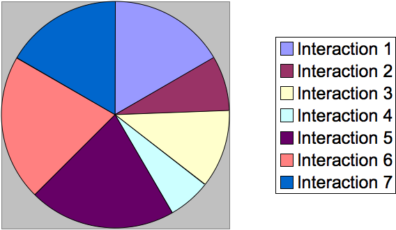
An Interaction is a defined flow of messages between one or more Locations. The Interaction is a complete message exchange that accomplishes a business operation. SPECjms2007 defines seven (7) Interactions of varying complexity and length.
A Flow Step is a single step of an Interaction. An Interaction therefore is comprised of multiple Flow Steps.
An Event Handler (EH) is a Java Thread that performs the messaging logic of a single Flow Step. A Flow Step may use multiple Event Handlers to accomplish all of its messaging as required by the benchmark. In relation to the SPECjms2007 benchmark, the Clients are the Event Handlers, which are the components in which all JMS operations are performed.
A Driver (DR) is an Event Handler that does not receive any JMS messages. Drivers are those Event Handlers that initiate Interactions by producing JMS messages. Although they are only the initiators in the JMS message flow and not JMS message receivers, they are included collectively under Event Handlers as they are modelling the handling of other, non-JMS business events (e.g. RFID events) in the benchmark application scenario.
The System Under Test (SUT) is comprised of all hardware and software components that are being tested. The SUT includes all the Server machines and Client machines as well as all hardware and software needed by the Server and Clients.
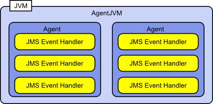
An Agent is a collection of Event Handlers (EHs which includes DRs) that are associated with a Location. A Location can be represented by multiple Agents.
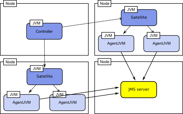
An AgentJVM is a collection of Agents that run in a single Java Virtual Machine (JVM).
The Controller (also referred to as the ControlDriver) is the benchmark component that drives the SPECjms2007 benchmark. There is exactly one Controller when the benchmark is run. The Controller reads in all of the configuration, instantiates the Topology (the Locations to use and connections between them), monitors progress, coordinates phase changes and collects statistics from all the components.
A Satellite (also referred to as a SatelliteDriver) is the benchmark component that runs AgentJVMs and is controlled by the Controller.
The Framework is the collective term used for the Controller, Satellite and benchmark coordination classes.
A Node is a machine in the SUT. The four kinds of nodes are, server nodes, client nodes, db nodes, and other nodes. A server-node is any node that runs the JMS Provider's server software. The client-nodes run the benchmark components and must each run exactly one Satellite. If the JMS product is configured with a database which runs on machines that are separate from the ones that the JMS server software runs on, then these machines are referred to as database nodes. Any other machines that are needed for the JMS product operation that are not covered by the three nodes described above are included in other nodes.
The Delivery Time refers to the elapsed time measured between sending a specific message and that message being received.
Normal Operation refers to any time the product is running, or could reasonably be expected to run, without failure.
A Typical Failure is defined as a failure of an individual element (software or hardware) in the SUT. Some examples to qualify this include Operating System failure, interruption to electricity or networking or death of a single machine component (network, power, RAM, CPU, disk controller, or an individual disk, etc). It includes failure of the Server as well as Clients.
A Single-Point-of-Failure is defined as a single Typical Failure. It is not extended to cover simultaneous failures or larger scale destruction of resources.
Non-Volatile Storage refers to the mechanism by which persistent data is stored. Non-Volatile Storage must be online and immediately available for random access read/write. Archive storage (e.g. tape archives or other backups) does not qualify as it is not considered as online and immediately available.
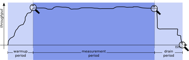
The Measurement Period refers to length of time during which measurement of the performance of the SUT is made.
The Warmup Period refers to the period from the commencement of the benchmark run up to the start of the Measurement Period.
The Drain Period refers to the period from the end of the Measurement Period up to the end of the benchmark run.
The Final Version refers to the final version of a product that is made available to customers.
The Proposed Final Version refers to a version of a product, that while not a final version as defined above, is final enough to use to submit a benchmark result. Proposed final versions can include Beta versions of the product.
The General Availability (GA) date for a product is the date that customers can place an order for, or otherwise acquire the product.
The Run Result refers to the HTML file that is generated at the end of a benchmark run that indicates the pass/fail status of all the Interactions in the benchmark.
A Result Submission refers to a single JAR file containing a set of files describing a SPEC benchmark result that is submitted to SPEC for review and publication. This includes a Submission File, a Configuration Diagram and a Full Disclosure Archive.
The Submission File refers to an XML-based document providing detailed information on the SUT components and benchmark configuration, as well as some selected information from the benchmark report files generated when running SPECjms2007. The Submission File is created using the SPECjms2007 Reporter.
The Configuration Diagram refers to a diagram in common graphics format that depicts the topology and configuration of the SUT for a benchmark result.
The Full Disclosure Archive (FDA) refers to a soft-copy archive of all relevant information and configuration files needed for reproducing the benchmark result.
The Full Disclosure Report (FDR) refers to the complete report that is generated from the Submission File. The FDR is the format in which an official benchmark result is reported on the SPEC Web site.
The SPECjms2007 Reporter refers to a standalone utility provided as part of the SPECjms2007 Kit that is used to prepare a Result Submission. The SPECjms2007 Reporter generates the Submission File and gathers all information pertaining to the Result Submission into a directory to be packaged and submitted to SPEC for review and publication. The SPECjms2007 Reporter also generates a preview of the Full Disclosure Report to be verified by the submitter before submitting the result.
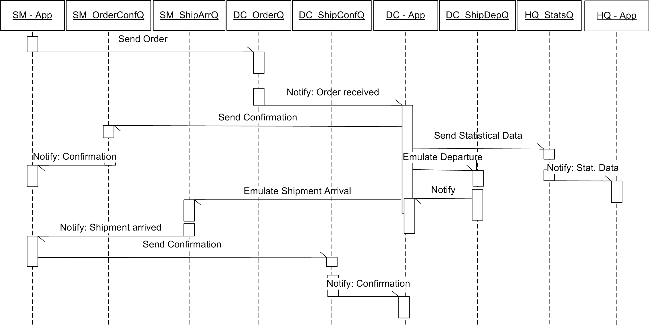
This Interaction models order and shipment handling between SMs and DCs. It exercises persistent P2P messaging.
The Interaction includes the following steps:
order message). orderConf message)
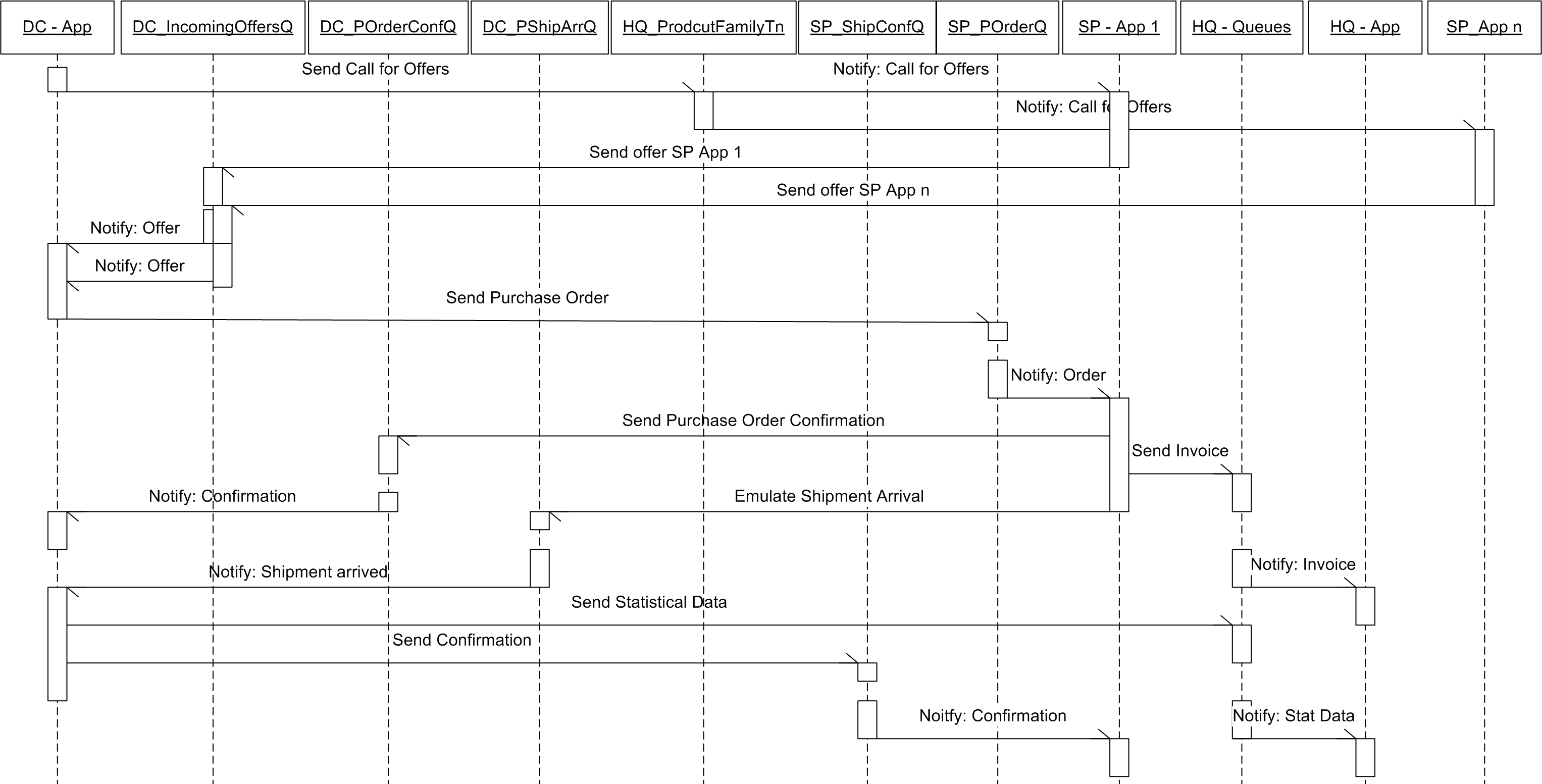
and ships the ordered goods. shipDep message). shipInfo message). statInfoOrderDC message). shipConf message). When goods in a DC are depleted, the DC has to order from a SP to refill stock. First, a SP has to be selected. The DC sends a call for offers to all SPs that are supplying the respective types of goods. The SPs send offers to the DC, the DC selects one of them and places a purchase order based on the offer. The selected SP receives the order, delivers the goods to the DC and sends an invoice to the Supermarket HQ. After receiving the shipment, the DC acknowledges receipt and reports it to the HQ. The Interaction uses both P2P and pub/sub communication and is illustrated in Figure 3.
Interaction 2 includes the following steps:
callForOffers message).offer messages).pOrder message).pOrderConf message)
to the DC and an invoice (invoice message) to
the HQ. It then ships the ordered goods.pShipInfo message).pShipConf message).statInfoShipDC message).Every Supplier offers products of exactly m product families. For every prodcut family of the n product families exists one topic.
Selling prices are changed by the company administration from time to
time. To communicate this, the company HQ sends messages (priceUpdate)
with pricing information to the Supermarkets. The communication here
is one-to-many and is based on pub/sub messaging.
This Interaction exercises persistent P2P messaging inside the SMs. It
is triggered when goods leave the warehouse of a Supermarket to refill
a shelf. This is registered by RFID readers and a message (inventoryInfo)
is sent to the local information system to update inventory. Note that
since incoming goods are part of another Interaction (i.e., Interaction
1), they are not considered here.
This Interaction exercises non-persistent P2P messaging between the SMs
and the HQ. It is triggered when SMs send sales statistics (statInfoSM messages)
to the HQ. HQ can use this data as a basis for data mining in order to
study customer behavior and provide useful information to marketing.
For example, based on such information, special offers or product discounts
could be made.
New products are announced by the company administration from time to
time. To communicate this, the company HQ send messages (productAnnouncement)
with product information to the Supermarkets offering the respective
product types. This communication is based on non-persistent, non-durable
pub/sub messaging.
HQ send credit card hot lists (creditCardHL messages) to
SMs. A complete list is sent once every hour and incremental updates
as required. This Interaction is used to exercise non-durable, non-persistent
pub/sub messaging.
Table 1 shows the Destinations (queues and topics) used in the implementation of the seven Interactions. Destination names are prefixed with the Location type they belong to (SP, SM, HQ or DC) and suffixed with 'T' or 'Q' depending on the Destination type (topic or queue).
| Interaction | Location | Destination JNDI Name | Message |
|---|---|---|---|
| 1 | DC | DC_OrderQ | order |
| 1 | DC | DC_ShipDepQ | shipDep |
| 1 | DC | DC_ShipConfQ | shipConf |
| 2 | DC | DC_IncomingOffersQ | offers |
| 2 | DC | DC_POrderConfQ | pOrderConf |
| 2 | DC | DC_PShipArrQ | pShipment |
| 1 | SM | SM_ShipArrQ | shipInfo |
| 1 | SM | SM_OrderConfQ | orderConf |
| 4 | SM | SM_InvMovementQ | inventoryInfo |
| 2 | SP | SP_POrderQ | pOrder |
| 2 | SP | SP_PShipConfQ | pShipConf |
| 1 | HQ | HQ_OrderDCStatsQ | statInfoOrderDC |
| 2 | HQ | HQ_ProductFamily<n>T | callForOffers |
| 2 | HQ | HQ_ShipDCStatsQ | statInfoShipDC |
| 2 | HQ | HQ_InvoiceQ | invoice |
| 3 | HQ | HQ_PriceUpdateT | priceUpdate |
| 5 | HQ | HQ_SMStatsQ | statInfoSM |
| 6 | HQ | HQ_ProductAnnouncementT | productAnnouncement |
| 7 | HQ | HQ_CreditCardHLT | creditCardHL |
Note 1: Topic "HQ_ProductFamily<n>T" represents a
given product family and is used for distributing callForOffers messages
in Interaction 2.
Note 2: Since the Company Headquarters are responsible for centrally managing the single topic hierarchy used, all topic names are prefixed with HQ.
The types of messages used are detailed in Table 2. Precise details on the message contents are given in Appendix B.
| Intr. | Message | Destination Type | Message Type | Size | Properties | Description |
|---|---|---|---|---|---|---|
| 1 | order | Queue | ObjectMessage | small to medium | Persistent, Transacted | Incoming orders from SMs including ordered products and other order information. |
| 1 | orderConf | Queue | ObjectMessage | small to medium | Persistent, Transacted | Confirmation sent by DC to SM confirming receipt of an order. |
| 1 | shipInfo | Queue | TextMessage | small to large | Persistent, Transacted | EPCs representing items in a shipment (registered by RFID readers as shipment leaves DC / enters SM). |
| 1 | shipDep | Queue | TextMessage | small to large | Persistent, Transacted | EPCs representing items in a shipment (registered by RFID readers as shipment leaves DC / enters SM). |
| 1 | shipConf | Queue | ObjectMessage | small to medium | Persistent, Transacted | Confirmation sent to DC to confirm shipment arrival at SM. |
| 2 | callForOffers | Topic | TextMessage | small to medium | Persistent, Transacted, Durable | Call for Offers send to all SP offering a product family (XML document). |
| 2 | offer | Queue | TextMessage | small to medium | Persistent, Transacted | Offer created by SPs based on callForOffers (XML document). |
| 2 | pOrder | Queue | TextMessage | small to medium | Persistent, Transacted | Incoming purchase order based from DC on an offer (XML document). |
| 2 | pOrderConf | Queue | TextMessage | small to medium | Persistent, Transacted | Confirmation sent by SP to DC confirming receipt of a purchase order (XML document). |
| 2 | pShipment | Queue | TextMessage | small to large | Persistent, Transacted | XML document describing an arriving shipment from SP (registered by RFID readers as they enter DC). |
| 2 | pShipConf | Queue | TextMessage | small to medium | Persistent, Transacted | Confirmation sent to SP to confirm shipment arrival at DC (XML document). |
| 2 | invoice | Queue | TextMessage | small to medium | Persistent, Transacted | Purchase order invoice sent by SP (XML document). |
| 1 | statInfoOrderDC | Queue | StreamMessage | small | Non-Persistent, Non-Transacted | Statistical information sent to HQ containing information on the transactions and flow of goods between SMs and DCs. |
| 2 | statInfoShipDC | Queue | StreamMessage | small | Non-Persistent, Non-Transacted | Statistical information sent to HQ containing information on the transactions and flow of goods between SPs and DCs. |
| 3 | priceUpdate | Topic | MapMessage | small | Persistent, Transacted, Durable | Price update sent to SM by HQ. |
| 4 | inventoryInfo | Queue | TextMessage | small to large | Persistent, Transacted | EPCs representing observed item movements in the inventory of a SM (registered by RFID readers). |
| 5 | statInfoSM | Queue | ObjectMessage | small to very large | Non-Persistent, Non-Transacted, AutoAck | Statistical information sent to HQ containing sales statistics. |
| 6 | productAnnouncement | Topic | StreamMessage | small to large | Non-Persistent, Non-Transacted, Non-Durable | Product announcements sent to SM by HQ. |
| 7 | creditCardHL | Topic | StreamMessage | small to large | Non-Persistent, Non-Transacted, Non-Durable | Credit card hotlist sent to SMs by HQ. |
In SPECjms2007, AUTO_ACKNOWLEDGMENT is used as acknowledgment
mode for all non-transactional sessions. The reason is that most real-world
applications do not use the other acknowledgment modes (CLIENT_ACKNOWLEDGMENT or DUPS_OK_ACKNOWLEDGMENT).
However, SPECjms2007 still offers the possibility to change the acknowledgment
mode for some of the messages (see org.spec.jms.Interaction7.autoAck property
in <topology>.properties), although this is not allowed
for published benchmark results.
A separate Event Handler is defined for each queue and topic. For maximal performance, multiple instances of an Event Handler could exist to enable parallel processing. The Event Handlers at the different Locations are part of the various applications emulated by the benchmark, e.g. the four Event Handlers of a DC represent the DC-App used in the diagrams in Figures 4 and 5. An Event Handler has a similar name to its respective Destination but is distinguished by an 'EH' suffix in place of 'Q' or 'T'.
The SPECjms2007 scenario includes many Locations represented by many Event Handlers. In order to drive the JMS Server to its capacity, Event Handlers may well be distributed across many Nodes. The reusable Framework designed to control SPECjms2007 aims to co-ordinate these distributed activities without any inherent scalability limitations. Key design decisions were that
In addition to controlling the benchmark cycle as described below the Controller also provides the following
The stages of the benchmark are as follows (corresponding text can be observed in output from the Controller).
The Controller component reads in all of the configuration and topological layout preferences given by the user. This will include items such as the number of different types of Location and lists of the Nodes across which they may be run. In the two submittable topologies, many of these values are either fixed or are automatically calculated based upon the scaling factor.
With this knowledge, the Controller instantiates the software components of the SUT. It begins this by starting an RMI server and connecting to a Satellite process on each Node machine identified as part of this test to give it specific instructions. In all places (throughout this benchmark) where lists are given, work is distributed equally using a simple round-robin algorithm.
The Satellite is a simple part of the Framework that knows how to build the correct environment to start the required JVM processes. It takes the Controller's configuration and starts the Agents relevant to that Node. Although each Agent is logically discrete from its peers, the Satellite will, based upon the user configuration, combine many Agents into a single AgentJVM for reasons of scalability. There is an architectural limit of one AgentJVM per class of Location (SP, SM, DC, HQ), meaning a minumum of four AgentJVMs in the SUT. Each Agent connects back to the Controller to signal their readiness.
The Controller signals all Agents to initialise their Event Handler threads and connect to the JMS resources they will be using (this includes both incoming and outgoing Destinations). Each Event Handler is implemented as a Java thread.
Load-generating threads (Drivers) ramp up their throughput from zero to their configured rate over the Warmup Period. This helps ensure the SUT is not swamped by an initial rush when many of its constituent elements may not yet be fully prepared.
The Agents are the only parts of the SUT which perform JMS operations (i.e. talk directly to the JMS Server).
The Measurement Period is also known as the steady-state period. All Agents are running at their configured workload and no changes are made. The Controller will periodically (thirty seconds by default) check there are no errors and may also collect periodic realtime performance statistics.
In order to make sure all produced messages have an opportunity to be consumed, the Controller signals Agents to pause their load-generating threads (Drivers). This period is not expected to be long in duration as a noticeable backlog in messages would invalidate audit requirements on throughput anyway.
The Controller takes formal measurements at three points during the run (see Figure 7). The first two, the beginning and end of the Measurement Period, are used to audit the messaging throughput. The final, at the end of the Drain Period, is used to audit the final message counts.
The Controller will also periodic measurements (via the realtime reporter) to display progress to users. These are not used as part of the auditting.
Agents will terminate all Event Handlers but remain present themselves so that the Controller can collect final statistics.
Having collected statistics from all parties, the Controller begins post-processing them into different reports. This process can take some time where the duration is related to total the number of Event Handlers involved in the benchmark. Large Horizontal Topologies may also require a significant Java heap size to post-process.
The Agents are logically isolated from each other, each intended to represent
a geographically distinct Location. For purposes of heap management and
simplicity, the Framework allows multiple Agents to be hosted within
the same AgentJVM. Agents communicate with the SPECj Framework via the
RMI-enabled org.spec.specj.Agent interface but are otherwise
self-contained (it is possible to run them without any Controller present).
The system for controlling the lifecycle of the Event Handler threads
is an extension of the reusable Performance Harness for JMS Framework
defined in org.spec.perfharness. The structure of these
classes is demonstrated in Appendices A.3 and A.4 whilst
the Performance Harness for JMS Framework can be found in Appendix A.7.
The logical isolation referred to above is enforced by the use of an IsolationClassLoader which separates the class structure of each Agent within a single JVM. This means static data cannot be shared between co-located Agents. If the JMS Client code makes use of JNI only one Agent in a JVM can be run successfully; the binary library cannot be loaded twice and there is no parent ClassLoader to hold a shared instance. In this case the configuration must set *.jvms_per_node=0 to ensure there is only a single Agent in each JVM.
Each Interaction is operated independently by its associated Driver. The input rate is scaled during the Warmup Period and fixed during the Measurement Period. For each Interaction Driver thread, cycle times (the delay between two message injections) are selected from a negative exponential distribution, computed from the following equation.
Tc = -ln(x) * Tm
where:
Tc = Cycle Time

    Tm = Mean desired cycle time

    ln = natural log (base e)

    x = random number, with at least 31 bits of precision, from a uniform
    distribution such that (0 < x <= 1)
The distribution is truncated at 5 times the mean. For each Interaction Driver, the current time is compared to the target time and, if this is greater than zero, the Driver will sleep for for difference. By this method, inaccuracies from the precision of getting the current time, sleeping for a fixed time and the time taken to compute cycles are removed from the system.
In addition to providing a standard workload and metrics for JMS performance, SPECjms2007 aims to provide a flexible framework for performance analysis of JMS Servers that allows users to configure and customize the workload according to their requirements. To achieve this goal, the Interactions are implemented in such a way that one could run them in different combinations depending on the desired transaction mix. SPECjms2007 provides three different workload topologies which correspond to three different modes in which the benchmark can be run:
The Horizontal Topology allows the workload to be scaled horizontally by increasing the number of Locations (SMs, DCs, SPs, HQs) while keeping the traffic per Location constant. In the Vertical Topology, a fixed set of Locations is used and the workload is scaled by increasing the rate at which goods are sold at Supermarkets. Finally, the Freeform Topology allows the user to define his own Topology and transaction mix and scale the workload in an arbitrary manner by increasing the number of Destinations and/or increasing the Interaction rates. Note that while in the Horizontal and Vertical Topology scaling is supported in a manner that preserves the relation to the modeled real-life business scenario, this does not necessarily apply to the Freeform Topology since the goal there is to give the user maximum flexibility.
Note: Although the modeled scenario has a single HQ Location, the benchmark allows multiple HQ instances to exist each with its own set of queues. The goal is to avoid the HQ queues becoming a bottleneck when scaling the number of SMs, DCs and SPs. It is assumed that messages sent to the HQ are distributed evenly among the HQ instances. Multiple HQ instances are considered as separate servers within the same Location.
SPECjms2007 provides the following workload configuration parameters that can be set by the user:
javax.jms.Connection objects shared amongst
Event Handler classes within a single Agent. AUTO_ACKNOWLEDGMENT should be used as acknowledgment
mode for Interaction 7. While in the Horizontal and Vertical topologies there are some restrictions as to which parameters can be changed by the user, these restrictions are relaxed in the Freeform Topology. This allows the user to precisely configure the workload and transaction mix to be generated and the way it is distributed among Client processes. The user can selectively turn off Interactions or change the rate at which they are run to shape the workload according to his requirements. At the same time, when running the Horizontal or Vertical Topology, the benchmark behaves as if the Interactions were interrelated according to their dependencies in the real-life application scenario.
The goal of scaling the Topology in a "horizontal" direction is to increase
the number of JMS Destinations and associated Event Handlers whilst maintaining
a fixed throughput per Destination. This is accomplished by locking the
Driver rates and defining the number of Locations in terms of the Horizontal
scaling value (org.spec.jms.horizontal.BASE). This is the
single property which controls the Horizontal Topology. Attempting to
override the Driver rates or change other properties which affect the
Topology is possible but the situation is detected and results cannot
be submitted. Tuning properties are still allowed.
This Topology would allow vendors to make use of horizontally scaled (e.g. clustered) hardware and software (within bounds of the Run Rules) to best implement the Topology.
The following table shows, how the different parameters are defined for the Horizontal Topology. Some of them are based on the BASE parameter, some are fixed.
| Parameter | Fixed value |
|---|---|
| No. of SMs | BASE |
| No. of SPs | RoundUp(BASE*0.4) |
| SMs Per DC | 5 |
| No. of Product Families (Topics) | BASE |
| Interaction 1 Injection Rate | 1.539201540 |
| Interaction 2 Injection Rate | 2.133333334 |
| Interaction 3 Injection Rate | 6.000000000 |
| Interaction 4 Injection Rate | 3.378378378 |
| Interaction 5 Injection Rate | 11.544011544 |
| Interaction 6 Injection Rate | 11.385199240 |
| Interaction 7 Injection Rate | 9.230769230 |
| Number Cash Desks | 5 |
| ProductFamilies offered per SP | 5 |
| CRC frequency | 1000 |
| Interaction 7 Auto Ack | true |
| SM_Interaction1DR.msg.prob.1 | 95 |
| SM_Interaction1DR.msg.prob.2 | 4 |
| SM_Interaction1DR.msg.prob.3 | 1 |
| SM_Interaction1DR.msg.size.1 | 5 |
| SM_Interaction1DR.msg.size.2 | 100 |
| SM_Interaction1DR.msg.size.3 | 700 |
| DC_Interaction2DR.msg.prob.1 | 95 |
| DC_Interaction2DR.msg.prob.2 | 4 |
| DC_Interaction2DR.msg.prob.3 | 1 |
| DC_Interaction2DR.msg.size.1 | 3 |
| DC_Interaction2DR.msg.size.2 | 35 |
| DC_Interaction2DR.msg.size.3 | 200 |
| SM_Interaction4DR.msg.prob.1 | 95 |
| SM_Interaction4DR.msg.prob.2 | 4 |
| SM_Interaction4DR.msg.prob.3 | 1 |
| SM_Interaction4DR.msg.size.1 | 10 |
| SM_Interaction4DR.msg.size.2 | 100 |
| SM_Interaction4DR.msg.size.3 | 500 |
| SM_Interaction5DR.msg.prob.1 | 95 |
| SM_Interaction5DR.msg.prob.2 | 4 |
| SM_Interaction5DR.msg.prob.3 | 1 |
| SM_Interaction5DR.msg.size.1 | 2 |
| SM_Interaction5DR.msg.size.2 | 7 |
| SM_Interaction5DR.msg.size.3 | 13 |
| HQ_Interaction6DR.msg.prob.1 | 95 |
| HQ_Interaction6DR.msg.prob.2 | 4 |
| HQ_Interaction6DR.msg.prob.3 | 1 |
| HQ_Interaction6DR.msg.size.1 | 100 |
| HQ_Interaction6DR.msg.size.2 | 10 |
| HQ_Interaction6DR.msg.size.3 | 1000 |
| HQ_Interaction7DR.msg.prob.1 | 95 |
| HQ_Interaction7DR.msg.prob.2 | 4 |
| HQ_Interaction7DR.msg.prob.3 | 1 |
| HQ_Interaction7DR.msg.size.1 | 50 |
| HQ_Interaction7DR.msg.size.2 | 500 |
| HQ_Interaction7DR.msg.size.3 | 3000 |
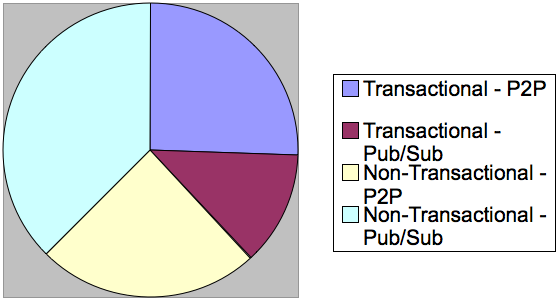
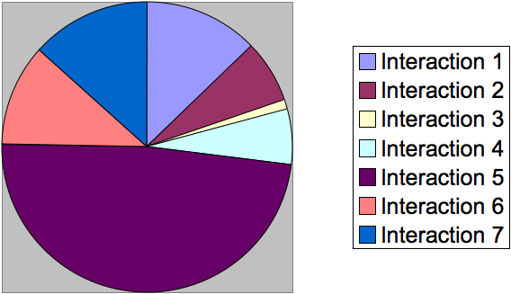
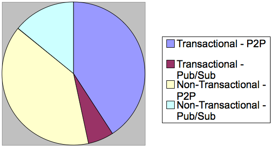
The ratios between transactional and non-transactional messages as well as the proportions between Pub/Sub and P2P are shown below.
| Messaging Type | Number of Messages | Number of Bytes |
|---|---|---|
| Transactional - P2P | 25.55% | 23.74% |
| Transactional - Pub/Sub | 12.45% | 2.41% |
| Non-Transactional - P2P | 24.55% | 49.19% |
| Non-Transactional - Pub/Sub | 37.46% | 24.66% |
The goal of scaling the Topology in a "Vertical" direction is to increase
the throughput per JMS Destination whilst maintaining a fixed number
of those Destinations. This is accomplished by locking the number of
Locations to a small set and defining rates in terms of the Vertical
scaling value (org.spec.jms.vertical.BASE). This is the
single property which controls the Vertical Topology. Attempting to override
the number of Locations or change other properties which affect the Topology
is possible but the situation is detected and results cannot be submitted.
Tuning properties are still allowed.
This Topology would allow vendors to make use of larger individual pieces of hardware or greater software multithreading to best implement the Topology.
The following table shows, how the different parameters are defined for the Vertical scenario. Some of them are based on the BASE parameter, some are fixed.
| Parameter | Fixed value |
|---|---|
| No. of SMs | 10 |
| No. of SPs | 5 |
| SMs Per DC | 5 |
| No. of HQs | 2 |
| No. of Product Families (Topics) | 100 |
| Interaction 1 Injection Rate | 0.076190476*BASE |
| Interaction 2 Injection Rate | 0.106666667*BASE |
| Interaction 3 Injection Rate | 0.05*BASE |
| Interaction 4 Injection Rate | 0.162162162*BASE |
| Interaction 5 Injection Rate | 0.577200577*BASE |
| Interaction 6 Injection Rate | 0.142314991*BASE |
| Interaction 7 Injection Rate | 0.102564103*BASE |
| Number Cash Desks | 5 |
| ProductFamilies offered per SP | 50% |
| CRC frequency | 200*BASE |
| Interaction 7 Auto Ack | true |
| SM_Interaction1DR.msg.prob.1 | 95 |
| SM_Interaction1DR.msg.prob.2 | 4 |
| SM_Interaction1DR.msg.prob.3 | 1 |
| SM_Interaction1DR.msg.size.1 | 5 |
| SM_Interaction1DR.msg.size.2 | 100 |
| SM_Interaction1DR.msg.size.3 | 700 |
| DC_Interaction2DR.msg.prob.1 | 95 |
| DC_Interaction2DR.msg.prob.2 | 4 |
| DC_Interaction2DR.msg.prob.3 | 1 |
| DC_Interaction2DR.msg.size.1 | 3 |
| DC_Interaction2DR.msg.size.2 | 35 |
| DC_Interaction2DR.msg.size.3 | 200 |
| SM_Interaction4DR.msg.prob.1 | 95 |
| SM_Interaction4DR.msg.prob.2 | 4 |
| SM_Interaction4DR.msg.prob.3 | 1 |
| SM_Interaction4DR.msg.size.1 | 10 |
| SM_Interaction4DR.msg.size.2 | 100 |
| SM_Interaction4DR.msg.size.3 | 500 |
| SM_Interaction5DR.msg.prob.1 | 95 |
| SM_Interaction5DR.msg.prob.2 | 4 |
| SM_Interaction5DR.msg.prob.3 | 1 |
| SM_Interaction5DR.msg.size.1 | 2 |
| SM_Interaction5DR.msg.size.2 | 7 |
| SM_Interaction5DR.msg.size.3 | 13 |
| HQ_Interaction6DR.msg.prob.1 | 95 |
| HQ_Interaction6DR.msg.prob.2 | 4 |
| HQ_Interaction6DR.msg.prob.3 | 1 |
| HQ_Interaction6DR.msg.size.1 | 100 |
| HQ_Interaction6DR.msg.size.2 | 10 |
| HQ_Interaction6DR.msg.size.3 | 1000 |
| HQ_Interaction7DR.msg.prob.1 | 95 |
| HQ_Interaction7DR.msg.prob.2 | 4 |
| HQ_Interaction7DR.msg.prob.3 | 1 |
| HQ_Interaction7DR.msg.size.1 | 50 |
| HQ_Interaction7DR.msg.size.2 | 500 |
| HQ_Interaction7DR.msg.size.3 | 3000 |
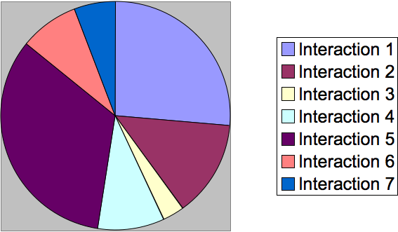
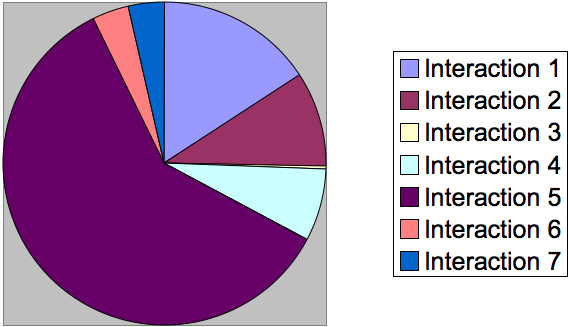
The ratios between transactional and non-transactional messages as well as the proportions between Pub/Sub and P2P are shown below.
| Messaging Type | Number of Messages | Number of Bytes |
|---|---|---|
| Transactional - P2P | 40.74% | 29.52% |
| Transactional - Pub/Sub | 5.99% | 2.25% |
| Non-Transactional - P2P | 39.09% | 61.03% |
| Non-Transactional - Pub/Sub | 14.19% | 7.19% |
Freeform topologies are intended to allow experimentation with the benchmark. The two submittable topologies (Horizontal and Vertical) are controlled by fixing certain properties into values or ratios. In all other respects they are the same as Freeform Topology which contains those same variables but provides no restrictions on their use. When in freeform mode no checking is done on the validity of the defined Topology.
This allows users (and developers!) to define their own workloads using the full set of configurable parameters given by SPECjms2007.
The following is a diagram demonstrating the interaction of the major packages which comprise the benchmark. Not visualised but of note are:
org.spec.jms.preauditor |
This contains a helper application which checks Destinations are clear and ready for a benchmark run. It utilises the location package and will therefore only audit Locations currently defined. Due to limitations of the JMS specification, this tool only checks that Queues are empty and performs no operation on Topics. |
org.spec.perfharness.jms.providers |
This package contains an interface, JMSProvider, which can be implemented to provide product-specific operations for the creation or lookup of JMS objects. Such implementations are packaged separately to the main benchmark. |
org.spec.jms.setup |
This contains an application which attempts to create the relevant JMS Destinations for the current configuration. This is only possible if a product-specific JMS provider class is configured which can actually perform the creation. In the default case, it simply lists the names of required Destinations. |
The following serves to highlight aggregation and inheritance within the org.spec.jms.location package.
The following serves to highlight aggregation and inheritance within the org.spec.jms.eventhandler package.
Only the eventhandler.hq package is used to demonstrate the relationships.
The following serves to highlight aggregation and inheritance within the org.spec.jms.agent package.
The following serves to highlight aggregation and inheritance within org.spec.jms.stats and org.spec.jms.results.
Not all results reporters are shown. Statistics are stored following
the Composite pattern and the resulting structure is parsed (by the results
classes) using a Visitor pattern.
The following serves to highlight aggregation and inheritance within org.spec.jms.framework and org.spec.specj.
The SPECjms2007 control classes and methodology are extended from the
SPECj Framework.
The following serves to highlight aggregation and inheritance within org.spec.perfharness.
The SPECjms2007 Agent classes and methodology are extended from ControlThread and WorkerThread whilst
product-specific plugins are extended from JNDI.
All communication between SPs and DCs/HQ is done via TextMessages containing
XML (inter-company communication).
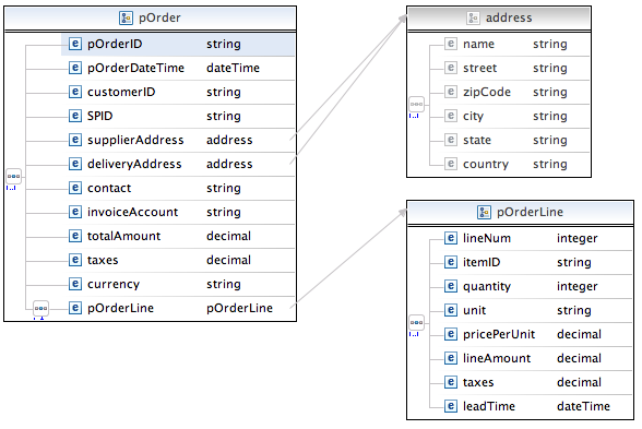
pOrder Message SchemapOrder is a TextMessage (in XML format) containing
a purchase order sent from DC to SP. The pOrder message
includes some header information (about the order, SP and
DC) and the pOrderLines (information about the ordered items).
The size of a message depends on the number of pOrderLines.
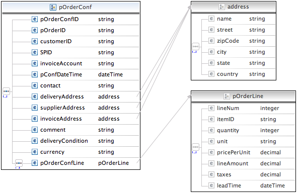
pOrderConf Message SchemapOrderConf is a confirmation message sent from SP to DC upon
receival of an order from the DC. It header information
and a list of confirmed pOrderLines. The size of pOrderConf is
similar to the size of the confirmed pOrder.

pShipInfo Message Schema This message emulates the observation of an incoming shipment by RFID readers at a DC's warehouse. An observation can contain different items as well as multiple instances of the same item. Multiple instances of an item are represented as a list of EPCs (tags) or as a single record containing an itemID (similar to an EPC) of a product and number of observed instances. A combination of both representations for a shipment is possible. Which representation is selected depends on the types of observed items. For example, if a pallet of cheese is delivered there is no need for a list containing tags of single cheese packages, however, if a shipment of notebooks arrives, the serial numbers of individual items are of interest.

pShipConf Message Schema This message emulates a confirmation sent from DC to SP to confirm the
receipt of a shipment. It contains confirmation header information (data
about the shipment, the DC and the SP) and for every observed item type
a pShipConfLine element containing the quantity received.
Every shipment is associated with a pOrder and for every pOrderLine of
the latter, a pShipConfLine is included in the pShipConf message.
The size of the message is small to medium, depending on the number of
different items ordered.
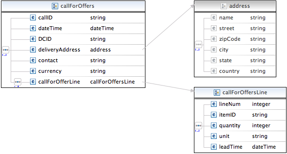
callForOffers Message Schema This message is sent when goods in a DC are depleted and the DC has to
order from a SP to refill stock. The DC sends a callForOffers message
to the HQ_ProductFamilynT topic corresponding to
the respective product family. SPs that can deliver the goods send offers
to the DC.
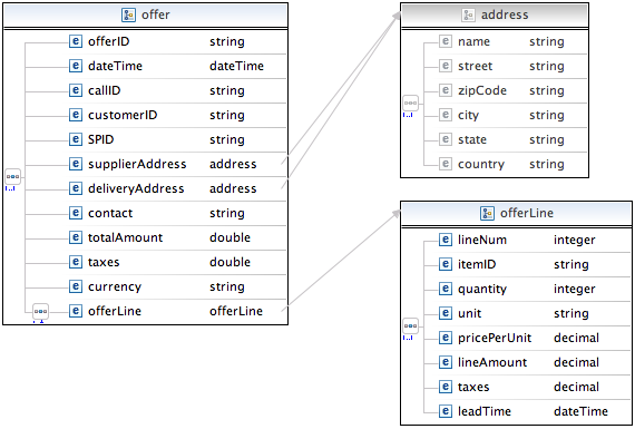
offer Message Schema An offer message is sent by a SP in response to a received callForOffers message.
It contains a list of the products with pricing information.
The data structures of the messages exchanged between SMs and DCs are
similar to the respective messages exchanged between DCs and SPs as discussed
in the previous section (e.g. orders and purchase orders). However, since
the communication between SMs and DCs is intra-company, there is no need
to use XML-based TextMessages and ObjectMessages can
be used instead. The only exception is for the shipInfo message,
which is implemented as a TextMessage similar to pShipment.
An order message is an ObjectMessage sent by a SM to a DC
containing an order. It is defined using three Java classes:
orderorderLineaddressThe size of an order message depends on the number of orderLines.
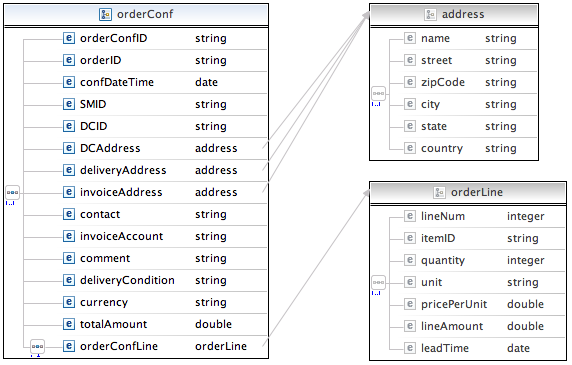
orderConf Message SchemaOrderConf is a confirmation sent by a DC to a SM upon receival
of an order from the SM. Like pOrderConf it contains some
header information and a list of confirmed orderLines. The size of an orderConf message
depends on the number of orderLines of the respective order.
OrderConf is defined using three Java classes:
orderConforderLineaddress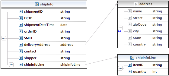
shipInfo Message SchemaSince shipment and pShipment represent nearly
the same information (EPC tag data observed by RFID readers), they have
a similar format.
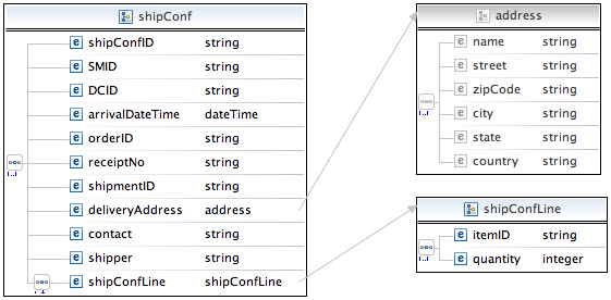
shipConf Message SchemaThis message is generated by SM to confirm shipment arrival. The data structure is mapped to two Java classes:
shipConfshipConfLineThe size of a shipConf message depends on the size of the
respective order.
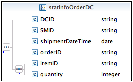
statInfoOrderDC Message SchemastatInfoOrderDC is a StreamMessage that contains
statistical information on SM orders received by a DC.
This message contains a stream of items shipped to a DC by a SP (purchase
order statistics). For every arriving shipment a separate message is
generated. The size depends on the number of items in the shipment. The
schema is identical to that of the shipConf message defined
in section B.2.4.
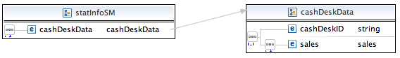
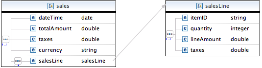
statInfoSM Message SchemaStatInfoSM contains sales statistics (e.g. for every cash
desk in a SM all sales made in a day or a sample of the sales). The data
structure is mapped to four Java classes:
statInfoSM (sales data for an entire SM, contains cashDeskData
objects)cashDeskData (sales data for a single cash desk, contains
sales objects)sales (a single sale, contains salesLine objects)salesLine (details of a sale)The size of statInfoSM messages would typically be very large.
Therefore they could be used to test JMS performance with large messages.
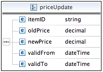
priceUpdate Message SchemapriceUpdate is a MapMessage sent by HQ to the
SMs. It contains pricing information for a single product.
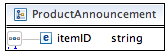
productAnnouncement Message
SchemaThe productAnnouncement StreamMessage is produced
by HQ and contains a list of product announcements. All products announced
in one message belong to the same product family (e.g. food, electronics,
...).

creditCardHL Message SchemaThis message is sent by the HQ to SMs periodically. It contains a list of revoked credit cards.
All communication between SPs and HQ is done via TextMessages containing
XML (inter-company communication).
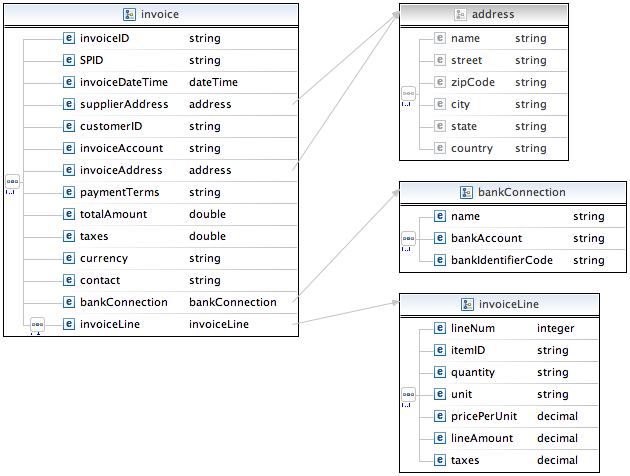
invoice Message SchemaThis message represents an invoice issued by a SP for a pOrder that
has been processed. For every pOrderLine of the pOrder,
the invoice contains an invoiceLine.
The shipDepature message has the same structure as the shipment message.

inventoryInfo Message SchemaThe message is sent when goods leave the warehouse of a SM (to refill a shelf). Goods are registered by RFID readers and the local warehouse application is notified so that inventory can be updated.